

Fuel system
Timing system
electrical equipment Complex tests
Vehicle sensors
Theory of diagnosis Do it yourself
MT Pro Accessories Score
Education Links
Home ![]() Articles
Articles ![]() Fuel system diagnostics – test ‘Injector balance’
Fuel system diagnostics – test ‘Injector balance’
Fuel system diagnostics – “Injector balance” test
The “Injector balance” test is designed to identify clogged and faulty injectors. The test is based on the assessment of pressure pulsations in the fuel system during the operation of the injectors.
There are two types of fuel systems most commonly encountered:
Rail-mounted RTD fuel rail mounted

RTD fuel system:
- Fuel Pressure Regulator (RPM)
- RTD Vacuum Port
- Injector
- Fuel Rail
- Intake Manifold
- Excess fuel drain pipe
- High-pressure fuel pipe (~3 bar)
- Fuel pump
- Fuel filter
- Fuel tank
Two pipes are connected to the fuel rail: the first is the fuel supply, and the second is the drain of excess fuel. The pressure regulator is a membrane overpressure regulator that maintains fuel pressure at 3 bar. Excess fuel is returned through the pressure regulator through the fuel return pipe to the fuel tank.
– System with RTD mounted on the fuel pump in the tank Fuel system with RTD installed in the tank: 1. Injector
2. Fuel rail 3. Intake manifold 4. High-pressure fuel pipe 5. Fuel pump with built-in RTD 6. Filter 7. Fuel tank

The installation position of the high-pressure fuel line, pressure regulator, and injectors depends on the design of the particular engine. The fuel pump is located in the fuel tank and delivers fuel at a pressure of at least 3 bar. Fuel flows
from the fuel tank to the high-pressure fuel line, from where it is evenly distributed by the fuel rail to the four nozzles. The amount of injected fuel depends on the opening time of the injector.
The pressure regulator is installed at one end of the high-pressure fuel line. The direct connection of the pressure regulator to the intake manifold maintains a constant difference between intake manifold pressure and fuel pressure. Thus, the amount of injected fuel does not depend on the pressure in the intake manifold and depends only on the opening time of the injectors.
The function of the RTD is to maintain constant pressure in the fuel system. However, when the nozzle is opened, the pressure in the system drops abruptly, then gradually recovers. Consequently, there is a direct relationship: the more jumps when dumping fuel, the greater the fuel consumption through the nozzle. It is logical to conclude that by comparing pressure pulsations from different nozzles, one can assess their condition. It is not possible to track these
pulsations with a pressure gauge due to its inertia.
The change in pressure can be tracked by the deformation of the nozzles. A vibration sensor has been developed specifically for this purpose. It is installed on the fuel supply pipe and registers its deformation.
Installation of the sensor on the fuel system with RTD

The classic appearance of the fuel system with RTD on the rail:
- Fuel Injector
- Injector electrical connector
- Injector wiring
- Fuel supply pipe (high pressure)
- Fuel return pipe to the tank (low pressure)
- Fuel pressure regulator (RDT ) )
- Vacuum connection RTD
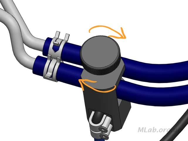
The sensor must be installed on the fuel supply pipe. Preliminarily clean the installation site from debris and oily deposits.

Position the sensor so that the tube is between the V-shaped part of the sensor and the clamping screw. The clamping screw should lightly touch the tube.

Note, the sensor should be located as close as possible to the fuel rail, but not closer than 2..3 cm from the edge of the rail fitting.

Check that the sensor body does not touch foreign pipes and wires, turn the clamping screw another 1.5 … 2 turns. When installing the sensor, do not apply great effort, as this may damage the fuel line. The sensitivity of the sensor is independent of the clamping screw tightening force.
Connect the sensor to the motor tester to any of the analog channels, for example, to the 6th. If at maximum sensitivity the signal amplitude is too small, then you can use an additional x5 hardware amplifier of the 8th channel.

 Connect the capacitive sensor of the first cylinder (Сх1) to the high-voltage wire of the first cylinder
For drainless ramps, connect the vibration sensor according to the same principle.

Motor-tester settings
Enable two channels: analog, to which the sensor is connected, and a logical channel. For the logical channel, select automatic tuning. The analog channel is set to the range of 0.1 0.2 V. For rubber pipes, a lower sensitivity is
required, and for plastic ones – a higher one. Sweep – 10 50 kHz.

Record the oscillogram with the engine fully warmed up and idling.

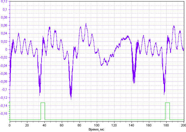
Oscillogram of pressure pulsations in the fuel rail:
1f – pulsation of the 1st injector 2f – 2nd injector
3f – 3rd injector 4f – 4th injector
Cx1 – spark moment in the first cylinder.
The height of each pulse corresponds to the capacity of the injector. The lower the tip of the pulse, the more fuel the injector injected.
An example of an oscillogram from the same car BEFORE washing the injectors
A test on the stand showed that the 3rd injector was partially clogged, the 1st – almost completely. Author: Evgeny Kurishko
Copyright © 2009-2022 MLab. All rights reserved


Ignition system
Classification of ignition systems
In a gasoline engine, the ignition of the fuel mixture is carried out by a spark discharge that o electrodes of the spark plug under the action of high voltage.
Ignition systems are subject to the following requirements:
- the voltage in the secondary circuit must be sufficient to break down the spark ga ensuring uninterrupted sparking (at least 16 kV when starting a cold and 12 kV wh engine);
- the spark formed between the spark plug electrodes must have sufficient energy for a working mixture (depending on its composition, density, and temperature);
- the moment of ignition must be strictly defined and correspond to the mode of ope
- the operation of all elements of the ignition system must be reliable at high-temperature loads;
- low level of radio interference during system operation.
Based on these requirements, any ignition system is characterized by the following main para
The time of energy accumulation by the coil (the angle of the closed state of the contacts moment the energy accumulation begins (specifically in the contact system – the moment the in other systems – the moment the power transistor operates) until the spark occurs (specifica
– the moment the contacts open interrupter or current cut-off by a transistor). This value char energy accumulated by the coil.
Breakdown voltage – the voltage in the secondary circuit at the moment of spark formation voltage in the secondary circuit. Ignition systems are calculated taking into account the second factor, which means that the maximum voltage developed by the coil always exceeds the brea worst engine operating conditions, it can reach 20 kV.
Burning voltage – the burning voltage of the electric arc, established in the secondary circuit the electrode gap. This value is much less than the breakdown voltage and amounts to units o
Burning time – the duration of the burning of the electric arc. The ignition of the fuel mixture burning, so the determination of its characteristics provides very important information in ass system.
Ignition advance angle (UOZ) – the angle by which the crankshaft has time to turn from th until the corresponding cylinder reaches top dead center (TDC). It is optimal to ignite the mix approaches the top dead center in the compression stroke, so that after the piston reaches TD to gain maximum pressure and perform maximum useful work on the stroke.
Any ignition system is clearly divided into two parts:
- low-voltage (primary) circuit – includes the primary winding of the ignition coil and th interrupter, switch and other components directly connected to it, depending on the de system.
- high-voltage (secondary) circuit – includes the secondary winding of the ignition coil, distribution system, high-voltage wires, candles.

Scheme of the simplest ignition system
-
- power source – rechargeable battery (battery) or generator;
- voltage converter – converts the direct voltage of the car’s on-board network into
- energy accumulation control device – determines the moment of the beginning o and the moment of ignition;
- ignition distributor – switches the ignition coil with one of the candles in accordanc operation of the cylinders;
- spark plugs – necessary for the formation of a spark discharge and ignition of the fu combustion chamber.
Candles are installed in the cylinder head. When a high voltage pulse is applied to the spark p between its electrodes, which ignites the working mixture. As a rule, one candle per cylinder i there are more complex systems with two candles per cylinder.
Systems with mechanical power distributor
Classic (distributor) ignition system , quite common among obsolete cars.

Schematic diagram of a classic ignition system
- ignition switch;
- power supply;
- capacitor;
- ignition coil;
- mechanical interrupter;
- breaker shaft;
- spark plugs;
- distributor.
Ignition distributor, distributor (distributor) – distributes high voltage from the coil to th cylinders. On contact ignition systems, as a rule, it is combined with a breaker, on non-contac sensor, on more modern ones it is either absent or combined with an ignition coil (while the c absent), a switch and sensors.
The distributor works as follows. The high voltage generated in the secondary winding of the i the central terminal of the ignition distributor. The rotating distributor rotor (slider) forms a co terminal and external electrodes in such a sequence that a high voltage is directed to the spar which the piston is at the end of the compression stroke, and creates a spark there. As a rule, engines, the cylinder sequence is 1-3-4-2. This order of operation of the cylinders is set to ev on the crankshaft of the engine. Synchronization with the crankshaft is ensured by the consta of the ignition distributor with the camshaft or any other shaft,
A mechanical interrupter is an energy storage control device that closes and opens the pow winding of the ignition coil, depending on the angle of rotation of the camshaft. The breaker c the cover of the ignition distributor.
A capacitor is connected in parallel with the contacts . It is necessary so that the contacts do of opening. During the breaking of contacts, a high voltage is formed between them, which le spark, but the capacitor absorbs most of the energy into itself and the spark is reduced to neg capacitor fails, the contacts of the breaker will be severely burned.
This system also contains mechanisms for adjusting the ignition timing: centrifugal and vacuu
The described system is simple in design. The disadvantages are the presence of unreliable m interrupter switches high currents, which eventually leads to its failure, sparking in the interru to radio interference.
One of the varieties of the classical system, partially devoid of the shortcomings of the choppe
system with a transistor switch .
The switch is a transistor key, which, depending on the control signal, turns on or off the po winding of the ignition coil. Depending on the device of a particular ignition system, the switch there can be several of them (if several coils are used in the ignition system).
In this case, the mechanical interrupter controls only the transistor switch, which in turn contr has a significant advantage over an interrupter without a transistor switch – it lies in the fact t interrupter switches a much lower current. Therefore, burning of the breaker contacts during eliminated, there is no need for a capacitor. The rest of the system is completely similar to the described ignition systems with a mechanical interrupter have a common name – contact ign

Schematic diagram of an ignition system with a mechanical interrupter and a transistor switch VT-power transistor.
Non-contact ignition systems (BSZ). In this case, instead of a mechanical interrupter, a se generator with a signal converter that controls only a transistor switch, which, in turn, control
Three types of sensors are used in transistorized switch ignition systems:
- Hall Sensor;
- inductive sensor;
- optical.
Over time, the additional task of the ignition switch was to charge the coil with the necessary ignition, the commutator must predict when to start charging the coil in order to get maximum overheating of the coil. Moreover, he must do this so that the charge time of the coil is approx
To do this, the switch calculates the speed of rotation of the motor and, depending on it, calcu closing the coil to the ground. In other words, the higher the engine speed, the sooner the sw coil to ground, but the closed state time will be the same.

General scheme of a contactless ignition system K – switch;
BD – contactless sensor;
Ignition systems with static energy distribution
These systems have a fundamental difference from those described above. DLI (Distributor energy distribution ignition systems do not have a mechanical distributor. The ignition coils are the spark plugs and the voltage distribution is carried out on the primary side of the ignition c which is subject to energy losses in them, as well as wear and tear, is also excluded. This met distribution is used in two versions: with single- and double-spark ignition coils.
Systems with single-spark ignition coils
In a single-spark system, each spark plug has its own individual ignition coil. The engine contr ignition coils in accordance with the established procedure for the operation of the cylinders. S loss in the distributor, these ignition coils can be very compact. Basically, they are located in dire plugs.
The fixed voltage distribution with single spark ignition coils is universally applicable to any nu are no restrictions on the ranges of ignition advance adjustment. An additional advantage is t and fails, only one cylinder will stop working, and the system as a whole will remain operation necessary to use a crankshaft rotation sensor in order to synchronize the operation of the enti rotational speed of this shaft.
The switch in such systems can be one unit for all ignition coils or separate units for each igni can be integrated into the electronic control unit, and can also be installed separately. Ignition separately and as a single unit (but in any case separate from the computer), and in addition, with switches.

General scheme of independent ignition systems
- high voltage wires;
- spark plugs;
EBU – electronic engine control unit; K – switch;
KZ – ignition coil.
One of the most popular varieties of such systems is the COP system (Coil on Plug – “coil o the ignition coil is placed directly on the candle. Thus, it became possible to completely get rid of components of the ignition system – high-voltage wires.

General scheme of the COP system
Dual Spark Coil (DIS) systems have one ignition coil for every two cylinders. The ends of the connection to spark plugs in different cylinders. The cylinders are chosen so that during the co-cylinder, the exhaust stroke occurs in the second (with an even number of cylinders). At the m spark is formed on both spark plugs; on the first coil, it gives a “working spark”, and on the se
For example, in a classic 4-cylinder engine in cylinders 1 and 4, the pistons occupy the same or bottom dead center at the same time) and move synchronously, but are on different cycles the compression stroke, cylinder 4 is on the exhaust stroke, and vice versa.

General scheme of the DIS system
Ignition coils in the DIS system can be installed either separately from the spark plugs and co-high-voltage wires, or directly on the spark plugs (as in the COP system, but in this case, high used to transfer the discharge to the spark plugs of adjacent cylinders).

General scheme of the “DIS-COP” system
Malfunctions in the ignition system lead to misfires of the fuel mixture in the cylinders, as a redeveloped power, is unstable, “troit”, the load on the working cylinders increases, which leads to operating time, and an increase in fuel consumption.
Author: Evgeny Kurishko
Copyright © 2009-2022 MLab. All rights reserved.


Ignition system DIS diagnostics
In the DIS ignition system, sparking occurs simultaneously in two cylinders.
High voltage is supplied to the spark plugs from two opposite terminals of the secondary wind coil, as a result of which the polarity of the high voltage pulses on the spark plugs of these cyl secondary circuits of the ignition coil does not have a galvanic connection with the “ground”, to obtain a high-quality oscillogram, it is necessary to use an ignition adapter (differential input

Schematic diagram of the DIS ignition system (the secondary circuit of the ignition coil is not the “ground”)

Design of the DIS ignition system with a dual DIS coil and a switch built into it
- Spark plug caps
- High-voltage wires
- Coil
- Ignition
coil wiring or 4-cylinder engines). Due to the different polarities of high voltage pulses in DIS ignition necessary to connect high voltage sensors during diagnostics in compliance with the polarity to determine the polarity, you can use the polarity detector. Polarity detection
It is necessary to press the button to turn on the detector, while two indicators (blue and red) indicate the health of the detector. Then alternately bring the detector to the high-voltage w If there are high voltage pulses in the wire, the corresponding indicator starts flashing: red – p negative. In accordance with the color of the glow, respectively marked capacitive sensors are DIS-4 or DIS-6 ( video with an example of polarity detection )

Positive polarity of the spark of the second cylinder
- Polarity detector
- Button to turn on the detector
- Indicator

Negative polarity of the spark of the third cylinder

Connecting high-voltage sensors to the ignition system in accordance with a certain polarity (t sensors should not be taken as a sample, it is only one of the possible options).
- Positive sensors (red marking)
- Negative sensors (blue marking)
It is desirable to connect the sensors closer to the ignition coil. If this is difficult to achieve due to the location of the ignition coil, then all sensors must be placed in the same conditions, either closer to the coil. If a set of capacitive sensors DIS-6 is used when diagnosing 4-cylinder engines do not need to be connected anywhere. It is desirable to take them out of the engine compart of interference.
Synchronization must be performed in accordance with the recommendations in the article “S synchronization. Label of the first cylinder»
Connection of high-voltage sensors to the motor-tester
Sensors with red marking must be connected to the 7th, and with blue marking – to the 8th c

Connecting high-voltage sensors to the MT-Pro motor-tester
1. To the positive polarity
sensors 2. To the negative polarity sensors
- To the synchronization sensor
Setting up the motor-tester software.
Further settings are given for the probes supplied with the MT Pro motor tester. The settings depend on the type of ignition system and the quality of the high-voltage wires.
All program settings are already contained in the working environment supplied with the prog to manually configure anything.

Selecting the appropriate work environment
After selecting the work environment, the program automatically switches to the secondary st
start the analysis, you must click the “Start” button.

Starting the analysis of the secondary voltage signal
If there are problems with the analysis, it is necessary to check the serviceability and correctn the HV sensors according to the initial oscillogram. To do this, stop the analysis and go to the
To diagnose the DIS of the ignition system, the motor-tester is provided with an ignition adap difference between the signals of positive and negative BB sensors. This allows you to visually similar to the classical ignition system, i.e. analyze the voltage on the coil, and not on the divi above):

Oscillogram of the secondary voltage DIS of the ignition system with the ignition adapter on
- MOC
- High voltage pulses + taking into account a false mark that is narrower / less)
It is acceptable for a DIS ignition system to have a false MOC that is narrower / less.

Oscillogram of the secondary voltage DIS of the false MOC
ignition system The ignition adapter is a pseudo-differential amplifier. The amplifier mode cont the 8th channel settings panel; it allows you to turn on one of two modes: normal operation o channels, and differential mode, as well as turn on an additional x5 hardware amplifier.

Button to turn on the ignition adapter
Depending on the selected mode, the button and the title of the tab will change appearance.
- adapter off, auxiliary amplifier off
![]()
![]()
![]()
![]()
![]()
![]()
![]()
![]()
- the adapter on, auxiliary amplifier off
- adapter off, auxiliary amplifier on
- adapter included, additional amplifier included

Schematic representation of differential channel operation (differential amplifier disabled). Wh a differential channel, it is recommended to disable the 7th channel.
If there are problems with the analysis of the oscillogram, it is necessary to check the compliance output of the sensors, for this, it is necessary to turn off the ignition adapter, and turn on the 7th c recording of the secondary voltage oscillogram. In this mode, both working and idle sparks the wi screen. It should be noted that the secondary voltage pulses on the 7th channel should be on
on the 8th – only negative.

Oscillogram of the secondary voltage DIS of the ignition system with the ignition adapter disc
- Working sparks
- Idle sparks
- Positive polarity (channel 7)
- Negative polarity (channel 8)
In case of the alternating polarity of the ignition pulses on one channel, it is necessary to repeat t determine the polarity.
When analyzing the oscillogram of the secondary voltage, it should be taken into account the cylinders are served by one coil, and, therefore, a malfunction of one cylinder will simultaneously pair the cylinder.
Author: Evgeny Kurishko
Copyright © 2009-2022 MLab. All rights reserved.